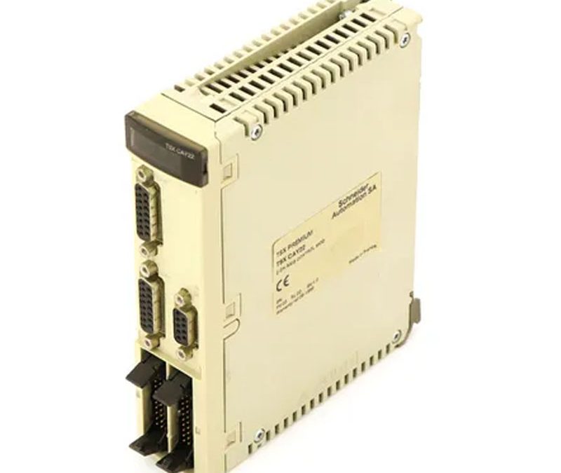
| Speed profile path |
Trapezoidal or parabolic |
| Resolution |
>= 0.5 position units per point
<= 1000 position units per point |
| Length of axis |
256…32000000 P |
| Acquisition speed |
<= 270000 points/mn
>= 54000 points/mn |
| Acceleration time |
8 ms…10 s |
| Operating mode |
FOLLOWER
OFF
Direct drive mode
Manual
Automatic |
| Type of axis |
Following axis dynamic ratio
Limited axis
Infinite axis |
| function of module |
Cut on the fly
Servo drive offset correction |
| I/O modularity |
2 axes |
| Input compatibility |
Incremental encoder 10…30 V totem pole
Incremental encoder 5 V DC RS422
With 2-wire/3-wire sensor (24 DC) auxiliary input
Absolute encoder parallel output ABE7CPA11
Absolute encoder SSI output 12…25 bits |
| Clock frequency |
200 kHz SSI absolute encoder |
| Incremental encoder frequency x1 |
500 kHz |
| Incremental encoder frequency x 4 |
1000 kHz in counting
250 kHz in input |
| Power dissipation in W |
7.2…11.5 W |
| Input type |
Current sink auxiliary input conforming to EN/IEC 1131 Type 2
Resistive servo drive control input conforming to EN/IEC 1131 Type 1
Resistive counter input |
| Input logic |
Positive |
| Input voltage |
24 V 8 mA auxiliary input
24 V 8 mA servo drive control input
5 V 18 mA counter input |
| Input voltage limits |
<= 5.5 V counter input
19…30 V auxiliary input
19…30 V servo drive control input |
| Voltage state 1 guaranteed |
>= 11 V for auxiliary input
>= 11 V for servo drive control input
>= 2.4 V for counter input |
| Current state 1 guaranteed |
>= 3.5 mA (servo drive control input)
>= 3.7 mA (counter input)
>= 6 mA (auxiliary input) |
| Voltage state 0 guaranteed |
<= 1.2 V for counter input
<= 5 V for auxiliary input
<= 5 V for servo drive control input |
| Current state 0 guaranteed |
<= 1 mA (counter input)
<= 1.5 mA (servo drive control input)
<= 2 mA (auxiliary input) |
| Input impedance |
270 Ohm for counter input
3000 Ohm for auxiliary input
3000 Ohm for servo drive control input |
| Number of outputs |
2 reflex output static conforming to EN/IEC 61131
2 analogue output static
2 servo drive validation output relay |
| Analogue output range |
+/- 10…24 V |
| analogue output resolution |
13 bits + sign |
| LSB value |
1.25 mV for analogue output |
| Output voltage |
24 V DC reflex output:
24 V DC servo drive validation output: |
| Output voltage limits |
Reflex output: 19…30 V
Servo drive validation output: 5…30 V |
| Nominal output current |
0.5 A for reflex output |
| Maximum output current |
1.5 mA analogue output
200 mA servo drive validation output
625 mA reflex output |
| Minimum load |
1 mA 1 V |
| Maximum voltage drop |
<1 V at state on for reflex output |
| Maximum leakage current |
0.3 mA for reflex output |
| Switching time |
< 5 ms for servo drive validation
< 500 µs for reflex output |
| Output compatibility |
Positive logic DC inputs (resistance <= 15 kOhm) for reflex |
| Short-circuit protection |
Current limiter reflex output
Thermal tripping reflex output |
| Output overload protection |
Current limiter reflex output
Thermal tripping reflex output |
| Output overvoltage protection |
Zener diode between outputs and 24 DC reflex output |
| Reverse polarity protection |
Reflex output: reverse diode on supply |
| Local signalling |
1 LED (green) for module operating (RUN)
1 LED (red) for external fault (I/O)
1 LED (red) for internal fault, module failure (ERR)
2 LEDs (green) for axis diagnostics available |
| Electrical connection |
1 connector HE-10 with 20 pins for aux inputs, reflex output, for external sensor and preactuator power supply
1 connector HE-10 with 20 pins for servo drive ctrl inputs + for ext power supply of servo drive inputs/outputs
1 connector SUB-D 9 for an analogue output (speed reference)
2 connectors SUB-D 15 for an incremental or absolute encoder |
| Current consumption |
11…20 mA at 24 V DC on 10/30 V absolute encoder module
1100 mA at 5 V DC
15 mA at 24 V DC |
| module format |
Standard |
| Net weight |
0.48 kg |
 Schneider